
Include the surrounding equipment
- Heavy decoiling
- Pre-punch or in-line punch stations
- Forming stands sized for thick strip
- Contour cutoff and long-beam packing
TAIBANG / EQUIPMENT
Form W-beam and thrie-beam highway guardrail profiles. Start with the drawing, strip thickness and hole layout.
APPLICATION & EQUIPMENT
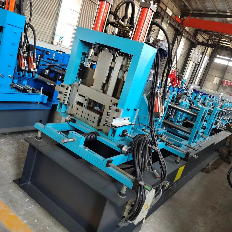
Highway guardrail equipment is discussed as forming, punching and cutting machinery for W-beam and thrie-beam profiles. Geometry, splice holes and post-connection details must come from the buyer drawing and from whatever independent product testing the buyer requires. This site does not claim highway-authority product approval for the formed beam. Reviewed workshop photographs of a hydraulic press station and a factory-hall forming line are general shop views. They are not photographs of a named guardrail model and do not show a highway installation.
YOUR SPECIFICATION BRIEF
Share the details you have. If a dimension or requirement is undecided, describe the intended finished product.
| Project item | What to include |
|---|---|
| Profile drawing | W-beam or thrie-beam section, cover width, corrugation depth and splice geometry. |
| Strip specification | Grade, thickness range, coating and coil width. |
| Hole layout | Slot and oval splice holes, post holes, pitch and edge distances. |
| Independent testing | Name any product standard or laboratory test the finished beam must meet; equipment supply is separate from that testing. |
| Workshop | Strip thickness handling, drive preference, cutoff method and packing of long beams. |
Speed, power, tooling, tolerances and control components belong in the agreed machine specification. They are not fixed across this equipment category.
ENGINEERING REFERENCE PARAMETERS
The following engineering baseline reflects measured workshop machine parameters and tooling standards. These figures are category references, not a fixed machine specification.
| Engineering Subsystem | Design Range & Workshop Baseline |
|---|---|
| Profile Discussion Range | W-beam (two-wave) and thrie-beam (three-wave) guardrail sections taken from the buyer drawing. This page does not treat a regional highway drawing as a certified product of this equipment. |
| Strip & Thickness Baseline | Engineering discussion range commonly covers heavy strip around 2.5 to 4.5 mm. Grade, coating and the maximum thickness the stands must form are confirmed per signed project. |
| Stand & Drive Baseline | Thicker strip and deeper corrugations usually need a heavier bed, larger shafts and a split gearbox or universal-joint drive. Stand count and shaft size are workshop baseline items until the section and thickness are fixed. |
| Punching & Cutoff Baseline | Splice slots and ovals may be punched on flat strip or in line. Contour cutoff dies follow the beam section. Sequence and station tonnage are discussed from the hole map, not published as a catalog rating. |
| Line Speed Discussion Range | Forming discussion for thick guardrail strip often sits around 8 to 15 meters per minute before punching and packing of long beams are included. Shift output must count those operations. |
| Standards Boundary | The formed profile can be manufactured to a drawing the buyer supplies. Highway-authority product approval, crash testing and installation certification are outside this equipment page and must be arranged independently if the project requires them. |
SPECIFICATION BOUNDARY
Specifications on this page are either verified brochure baselines or engineering discussion ranges. Final line layout, drive sizing, roll-stand count, tooling material, tolerances and acceptance criteria are confirmed in your signed project offer — they are not fixed by this page. Workshop photos and video show general shop arrangements and mechanical motion; they are not images of a named, quoted machine model.
* Engineering discussion range / workshop baseline; confirmed per signed project. This page describes forming equipment. It does not claim highway-authority product certification for the finished beam.
FROM BRIEF TO ACCEPTANCE
Confirm beam geometry from drawing
Review strip grade and thickness
Plan punching versus forming order
Agree cutoff and packing of long lengths
Record trial measurements against the drawing
WORKSHOP VIEWS / PROJECT DISCUSSION
Supplied workshop photos are reviewed shop views of a hydraulic press station and a factory-hall forming line. They are not photographs of a named W-beam or thrie-beam model and do not show a highway installation. This page describes forming equipment only; independent product testing, if required, is specified by the buyer.
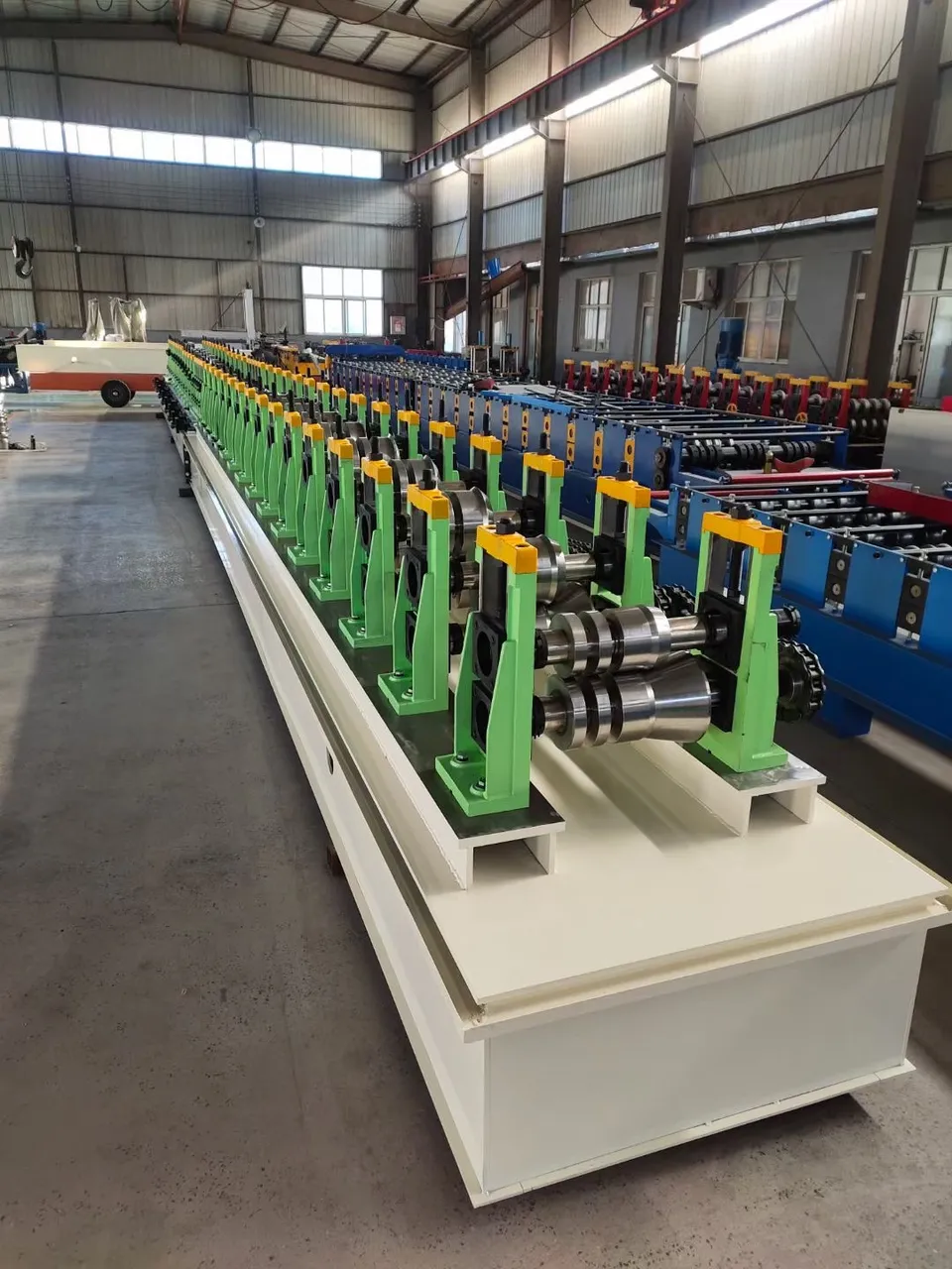
WORKSHOP VERIFICATION / HEAVY FORMING FRAME
Reviewed workshop footage of a blue forming machine during shop running. It shows bed, stands and motion, not a named W-beam or thrie-beam model and not a highway installation.
Silent workshop footage; it shows mechanical motion, not a quoted machine's output.
Plan your machine inspection ↗Record trial material, sample measurements, the operating cycle and the documents needed for acceptance.
Inspection planning ↗RELATED EQUIPMENT
These families are often specified together. Open a related line to compare the equipment scope.
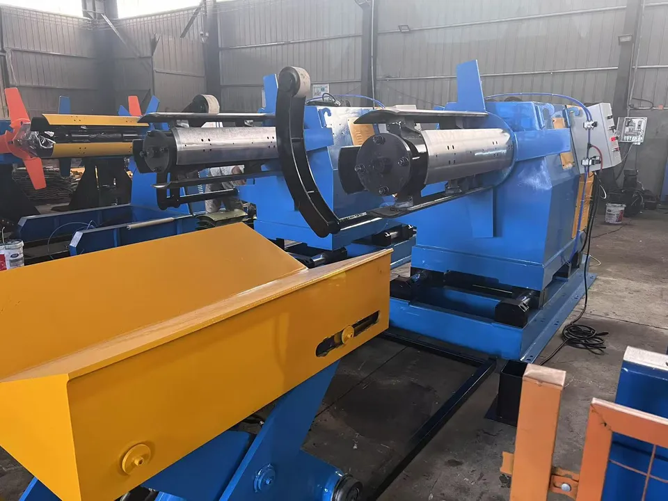
Form C, Z, U and Sigma structural purlins. Start with section sizes, thickness range and hole pattern.
Explore equipment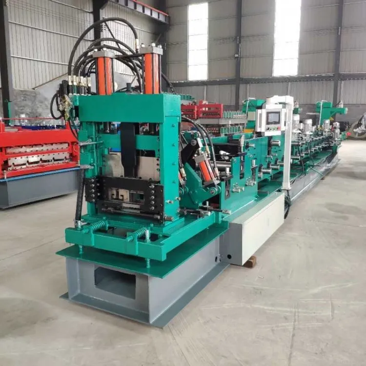
Form and punch pallet-rack and AS/RS uprights. Start with the section, hole pitch and thickness.
Explore equipmentBEFORE YOU REQUEST A QUOTE
Yes. Describe your intended panel or sheet in text. Contact info@tbrollforming.com to discuss sharing a sketch or reference image; this form does not upload files. Final tooling and pricing need an agreed technical brief.
Discuss the material, product geometry, length mix and full operating cycle. Forming speed alone does not describe finished output per shift.
Ask for a written offer that defines the equipment list, optional items, inspection, delivery terms, installation responsibilities and support scope.
Your next production line
Send your drawing, material, finished output target and destination. Build the equipment, inspection and delivery scope into one project brief.