
Include the surrounding equipment
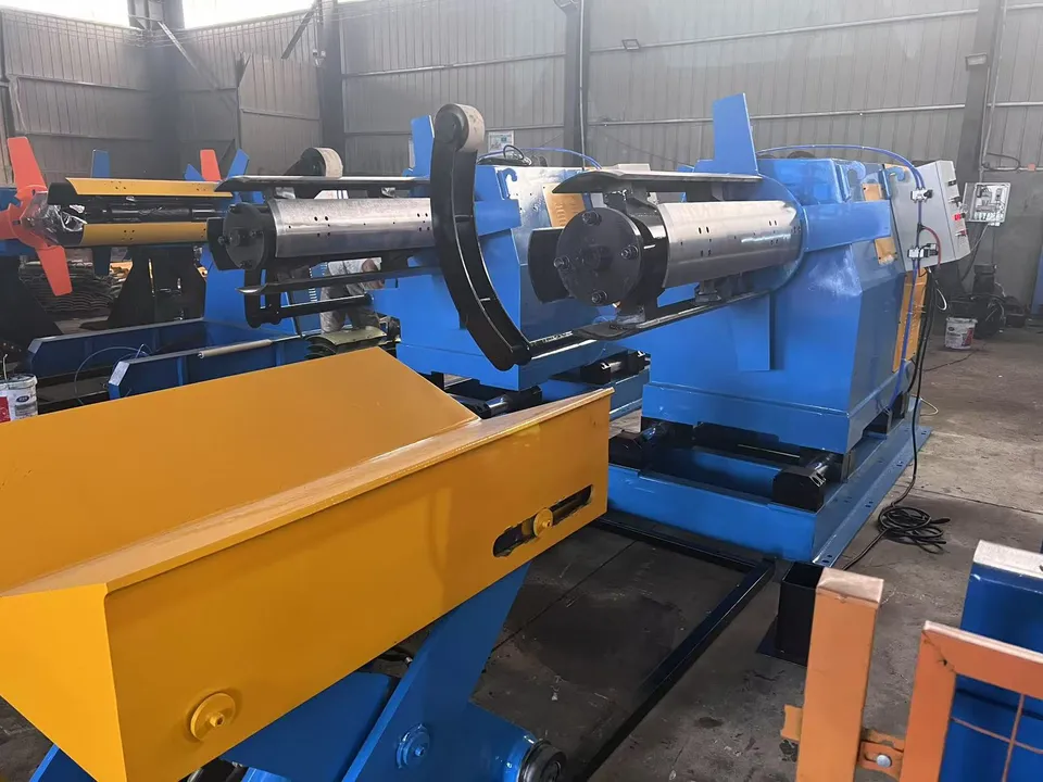
- Decoiling and leveling
- Servo or hydraulic punching
- Forming stands for the upright family
- Cutoff, stacking and scrap handling
TAIBANG / EQUIPMENT
Form and punch pallet-rack and AS/RS uprights. Start with the section, hole pitch and thickness.
APPLICATION & EQUIPMENT
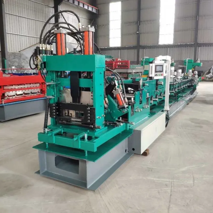
Warehouse racking uprights combine a structural channel or boxed section with a repeating hole pattern. The useful quotation starts from the upright drawing: web and return dimensions, steel grade, thickness, hole or teardrop pitch, and whether the line must also form associated beams or braces. Reviewed workshop photographs of a hydraulic punch station and forming stands are shown as general shop views. They are not photographs of a named AS/RS upright model.
YOUR SPECIFICATION BRIEF
Share the details you have. If a dimension or requirement is undecided, describe the intended finished product.
| Project item | What to include |
|---|---|
| Upright drawing | Section dimensions, returns, lips and any boxed or composite geometry. |
| Hole pattern | Shape, pitch, edge distance, tolerance discussion points and whether holes are punched before or after forming. |
| Coil specification | Grade, coating, thickness range and strip width. |
| Product mix | Upright lengths, batch sizes and whether beams or braces share the same line. |
| Workshop | Floor length, coil handling, punching scrap removal and finished-member stacking. |
Speed, power, tooling, tolerances and control components belong in the agreed machine specification. They are not fixed across this equipment category.
ENGINEERING REFERENCE PARAMETERS
The following engineering baseline reflects measured workshop machine parameters and tooling standards. These figures are category references, not a fixed machine specification.
| Engineering Subsystem | Design Range & Workshop Baseline |
|---|---|
| Section Discussion Range | Open or boxed racking uprights and, when requested in the same brief, related beams. Finished geometry is taken from the customer drawing; this page does not publish a proprietary hole standard. |
| Material & Thickness Baseline | Engineering discussion range commonly covers structural coil around 1.5 to 4.5 mm depending on bay load and upright family. Grade, coating and the heaviest strip the stands must form are confirmed per signed project. |
| Punching Layout Baseline | Repeating round, slot or teardrop patterns may use hydraulic or servo punching. Pitch accumulation over long uprights, tool-station count and scrap removal are workshop baseline topics until the hole map is agreed. |
| Forming & Drive Discussion | Stand count, shaft size and drive type are sized from section depth and thickness. Closed or high-return sections may need additional passes or a different cutoff die than an open channel. |
| Line Speed Discussion Range | Cycle discussion often sits around 6 to 15 meters per minute when punching density is moderate. Dense hole maps, thick strip and long members reduce usable output; shift targets must include punching and stacking time. |
| Electrical & Destination Requirements | Controls, voltage and guarding follow the project offer. No warehouse-system certification, seismic rating or named end-user rack brand is claimed on this page. |
SPECIFICATION BOUNDARY
Specifications on this page are either verified brochure baselines or engineering discussion ranges. Final line layout, drive sizing, roll-stand count, tooling material, tolerances and acceptance criteria are confirmed in your signed project offer — they are not fixed by this page. Workshop photos and video show general shop arrangements and mechanical motion; they are not images of a named, quoted machine model.
* Engineering discussion range / workshop baseline; confirmed per signed project. Media on this page is reused from reviewed workshop assets and does not depict a specific racking-upright model.
FROM BRIEF TO ACCEPTANCE
Confirm upright section and hole map
Review coil grade and thickness
Plan punching relative to forming
Agree cutoff and stacking
Inspect pitch and section on trial pieces
WORKSHOP VIEWS / PROJECT DISCUSSION
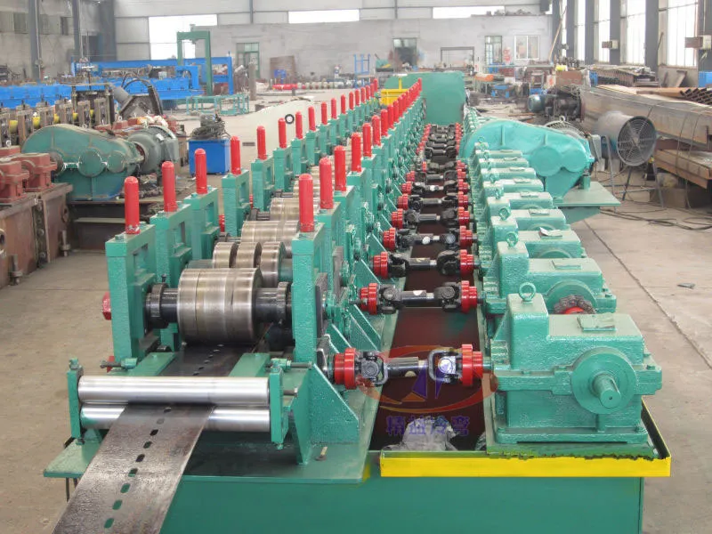
Supplied workshop photos are reviewed shop views of a hydraulic punch station and forming stands. They illustrate general line appearance, not a named pallet-rack or AS/RS upright model. Confirm the upright drawing, hole map and stacking method in the project offer.
WORKSHOP VERIFICATION / MULTI-STATION LINE
Reviewed workshop footage of a continuous multi-station line during commissioning. It shows shop controls and line length, not an AS/RS upright model or a warehouse installation.
Silent workshop footage; it shows mechanical motion, not a quoted machine's output.
Plan your machine inspection ↗Record trial material, sample measurements, the operating cycle and the documents needed for acceptance.
Inspection planning ↗RELATED EQUIPMENT
These families are often specified together. Open a related line to compare the equipment scope.
Form C, Z, U and Sigma structural purlins. Start with section sizes, thickness range and hole pattern.
Explore equipment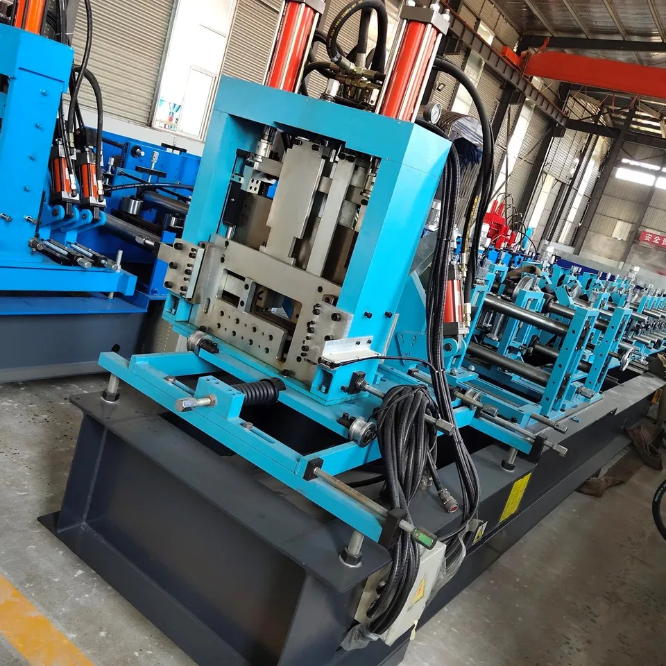
Form W-beam and thrie-beam highway guardrail profiles. Start with the drawing, strip thickness and hole layout.
Explore equipmentBEFORE YOU REQUEST A QUOTE
Yes. Describe your intended panel or sheet in text. Contact info@tbrollforming.com to discuss sharing a sketch or reference image; this form does not upload files. Final tooling and pricing need an agreed technical brief.
Discuss the material, product geometry, length mix and full operating cycle. Forming speed alone does not describe finished output per shift.
Ask for a written offer that defines the equipment list, optional items, inspection, delivery terms, installation responsibilities and support scope.
Your next production line
Send your drawing, material, finished output target and destination. Build the equipment, inspection and delivery scope into one project brief.