
Include the surrounding equipment
- Decoiling and leveling
- Adjustable-width forming stands
- Hydraulic cutoff
- Panel stacking and bundling
TAIBANG / EQUIPMENT
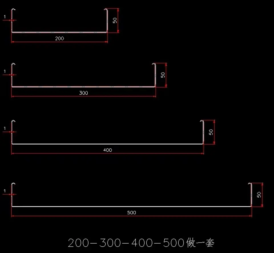
Form U-channel cargo box panels in multiple widths from a single set of tooling. Define the channel width range, flange height and material.
APPLICATION & EQUIPMENT
Cargo box panel equipment produces U-shaped channel profiles used for truck body sides, container panels and cargo enclosures. The key discussion point is the width range: a single set of roll tooling can produce multiple channel widths (e.g. 50–150 mm or 200–500 mm) by adjusting the forming stands. Specify the channel width family, flange height, material thickness and whether both size ranges should share one line or require separate tooling sets.
YOUR SPECIFICATION BRIEF
Share the details you have. If a dimension or requirement is undecided, describe the intended finished product.
| Project item | What to include |
|---|---|
| Channel width range | Width family: e.g. 50/100/150 mm or 200/300/400/500 mm; whether one tooling set must cover multiple widths. |
| Flange height | Standard 50 mm or custom; lip return if required. |
| Coil specification | Grade, coating, thickness range (typically 1.0–2.5 mm) and strip width. |
| Production target | Panels per shift, width mix and length variety. |
| Workshop | Floor space, coil handling, stacking method and electrical supply. |
Speed, power, tooling, tolerances and control components belong in the agreed machine specification. They are not fixed across this equipment category.
ENGINEERING REFERENCE PARAMETERS
The following engineering baseline reflects measured workshop machine parameters and tooling standards. These figures are category references, not a fixed machine specification.
| Engineering Subsystem | Design Range & Workshop Baseline |
|---|---|
| Profile Family | U-channel (open trough) cargo box panels. Two standard width families: 50/100/150 mm set and 200/300/400/500 mm set, each with 50 mm flange height. Custom width combinations available per project. |
| Material & Thickness Baseline | Hot-rolled or cold-rolled steel, galvanized or painted coil. Thickness discussion range: 1.0 to 2.5 mm. Strip width matched to the largest channel in the family plus forming allowance. |
| Forming & Changeover | Adjustable forming stands allow width changeover within the same family without replacing rolls. Stand count typically 8 to 14 depending on flange geometry and material thickness. |
| Cutoff & Handling | Hydraulic post-cut shear with length encoder. Cut length accuracy reference: within 1.5 mm. Automated stacking table for finished panels. |
| Line Speed Discussion Range | Continuous forming speed discussion: 10 to 20 meters per minute depending on material thickness and channel depth. Width changeover time: 10 to 20 minutes for manual adjustment. |
| Electrical & Destination Standards | Drive motors carry CE attestation (Certificate M.2023.206.C82549) under EU Machinery Directive 2006/42/EC and EMC Directive 2014/30/EU, verified by UDEM International through March 2028. Voltage, controls and guarding matched per project. |
SPECIFICATION BOUNDARY
Specifications on this page are either verified brochure baselines or engineering discussion ranges. Final line layout, drive sizing, roll-stand count, tooling material, tolerances and acceptance criteria are confirmed in your signed project offer — they are not fixed by this page. Workshop photos and video show general shop arrangements and mechanical motion; they are not images of a named, quoted machine model.
* Engineering discussion range / workshop baseline; confirmed per signed project. Profile drawings are factory-supplied CAD sections showing the standard width families.
FROM BRIEF TO ACCEPTANCE
Confirm channel width family and flange height
Review coil grade and thickness
Plan width changeover method
Agree cutoff and stacking
Measure trial panels against drawing
WORKSHOP VIEWS / PROJECT DISCUSSION
Supplied workshop photos are reviewed shop views of forming stands and line layout in the workshop. They illustrate general equipment appearance, not a specific cargo box panel model. Confirm channel width range, flange height and material in the project offer.
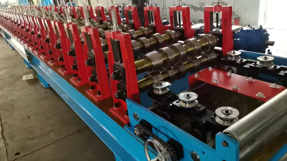
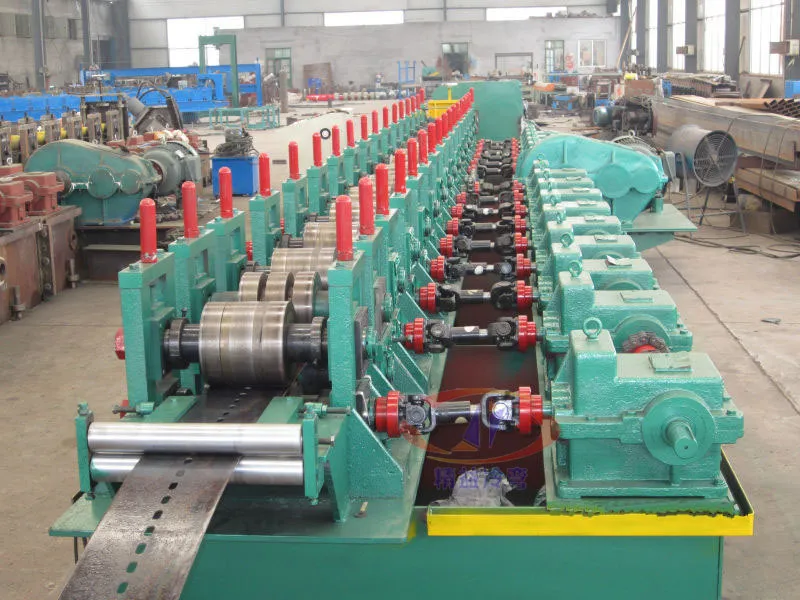
WORKSHOP VERIFICATION / CARGO PANEL FORMING
Workshop footage of hydraulic press and forming station for cargo box panel production line.
Silent workshop footage; it shows mechanical motion, not a quoted machine's output.
Plan your machine inspection ↗Record trial material, sample measurements, the operating cycle and the documents needed for acceptance.
Inspection planning ↗RELATED EQUIPMENT
These families are often specified together. Open a related line to compare the equipment scope.
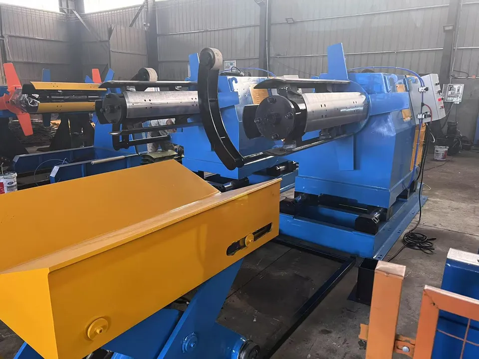
Slit, level and cut steel coils into strips or flat sheets. Start with coil width, thickness and the finished strip or sheet specification.
Explore equipment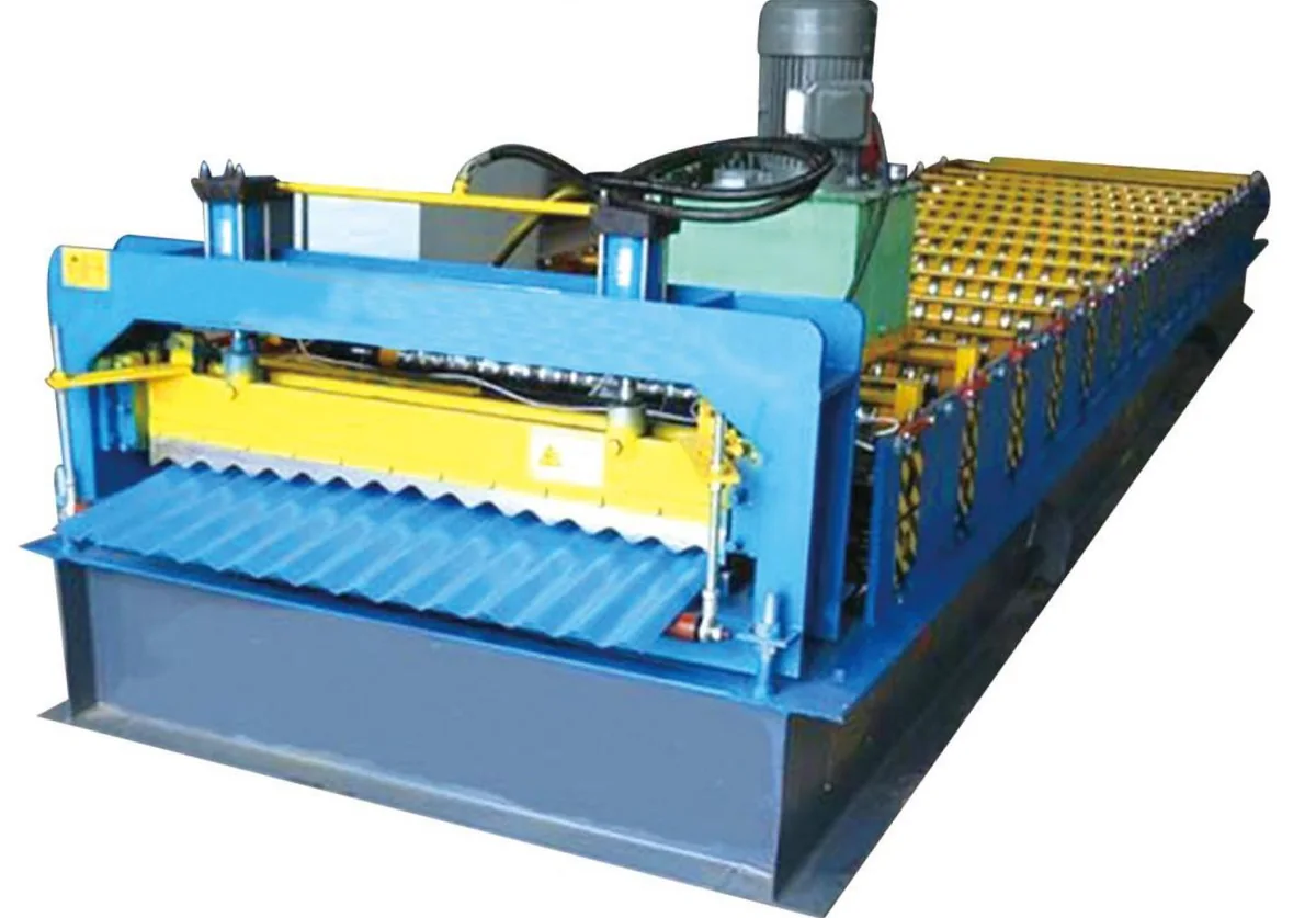
Form metal roofing and wall cladding. Match the profile, coil and finished sheet length.
Explore equipmentBEFORE YOU REQUEST A QUOTE
Yes. Describe your intended panel or sheet in text. Contact info@tbrollforming.com to discuss sharing a sketch or reference image; this form does not upload files. Final tooling and pricing need an agreed technical brief.
Discuss the material, product geometry, length mix and full operating cycle. Forming speed alone does not describe finished output per shift.
Ask for a written offer that defines the equipment list, optional items, inspection, delivery terms, installation responsibilities and support scope.
Your next production line
Send your drawing, material, finished output target and destination. Build the equipment, inspection and delivery scope into one project brief.